
Introduction
Fire accidents can cause severe damage to property and pose a significant threat to human life. Early detection is one of the most effective ways to prevent such disasters. In this project, we will build a simple Fire Alarm System using an Arduino board and an MQ-2 gas/smoke sensor.
This project continuously monitors the environment for smoke and combustible gases. When smoke levels exceed a predefined threshold, the system activates an LED indicator and a buzzer to alert nearby people.
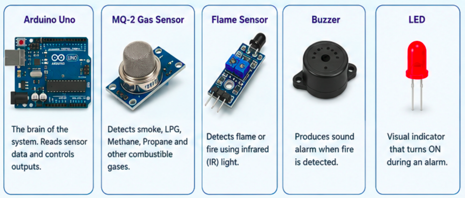
Components Required
- Arduino Uno (or compatible board)
- MQ-2 Gas/Smoke Sensor Module
- Flame Sensor Module
- Buzzer
- LED
- Jumper Wires
- Breadboard
- USB Cable
How It Works
The system uses two sensors:
1. MQ-2 Gas Sensor
The MQ-2 sensor detects smoke, LPG, methane, propane, hydrogen, and other combustible gases. The Arduino reads the analog value from the sensor and continuously monitors gas concentration levels.
2. Flame Sensor
The flame sensor detects infrared light emitted by fire. When a flame is detected, the sensor output changes and signals the Arduino.
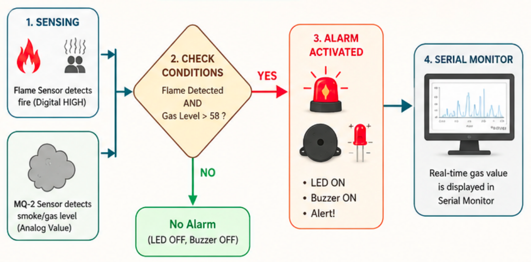
When both conditions indicate a potential fire hazard:
- The LED turns ON.
- The buzzer starts sounding.
- An alert is displayed on the Serial Monitor.
This combination helps reduce false alarms and improves detection reliability.
Arduino Code
const int analogInPin = A0;
const int digitalInPin = 8;
const int ledPin = 13;

const int mq2Pin = A1;

void setup()
{
  pinMode(digitalInPin, INPUT);
  pinMode(ledPin, OUTPUT);
  pinMode(3, OUTPUT);

  Serial.begin(9600);
}

void loop()
{
  int val;
  val = analogRead(mq2Pin);

  Serial.println(val);

  int analogVal = analogRead(analogInPin);
  boolean stat = digitalRead(digitalInPin);

  if (stat == HIGH && val > 58)
  {
    digitalWrite(ledPin, HIGH);
    tone(3, 358);
    delay(100);
  }
  else
  {
    digitalWrite(ledPin, LOW);
    noTone(3);
  }
}
Code Explanation
Pin Definitions
const int analogInPin = A0;
const int digitalInPin = 8;
const int ledPin = 13;
const int mq2Pin = A1;
These variables define the connections for the flame sensor, MQ-2 sensor, and LED.
Reading Sensor Data
val = analogRead(mq2Pin);
This reads the smoke or gas level from the MQ-2 sensor.
boolean stat = digitalRead(digitalInPin);
This reads the flame sensor's digital output.
Alarm Activation
if (stat == HIGH && val > 58)
The alarm activates when:
- Flame is detected.
- Smoke/gas level exceeds the threshold value (58).
Alert Mechanism
digitalWrite(ledPin, HIGH);
tone(3, 358);
The LED turns ON and the buzzer generates an audible alarm.
Circuit Connections
| Component | Arduino Pin |
| MQ-2 Analog Output | A1 |
| Flame Sensor Digital Output | D8 |
| LED Positive | D13 |
| Buzzer Positive | D3 |
| GND Connections | Arduino GND |
| VCC Connections | Arduino 5V |
Testing the System
- Upload the code to your Arduino.
- Open the Serial Monitor.
- Bring a lighter flame near the flame sensor (without touching it).
- Introduce a small amount of smoke near the MQ-2 sensor.
- The LED and buzzer should activate when both conditions are met.
Applications
- Home fire detection systems
- School and laboratory safety projects
- Industrial monitoring
- Smart home automation
- IoT-based safety systems
Possible Improvements
- Send SMS alerts using a GSM module.
- Trigger notifications via Wi-Fi using ESP8266/ESP32.
- Add an LCD display for real-time readings.
- Connect to a cloud dashboard for remote monitoring.
- Integrate temperature and humidity sensors.
Conclusion
This Arduino-based Fire Alarm System demonstrates how low-cost sensors can be combined to create an effective early-warning solution. By using both a flame sensor and an MQ-2 gas sensor, the system provides a simple yet practical approach to fire detection. It is an excellent project for students, beginners, and anyone interested in learning about embedded systems and safety automation.